Hydronic Balancing Valves Explained: Types, Working Principles & Cold-Climate Benefits (2026 Guide)
Hydronic balancing valves are critical components in modern HVAC systems. They ensure that heating and cooling water is distributed correctly to each branch, coil, and terminal unit. In cold-climate regions such as Ontario and Québec in Canada, and the U.S. Northeast and Midwest (New York, Boston, Chicago, Minnesota, etc.), hydronic heating is extremely common. Long heating seasons and high fuel costs make proper hydronic balancing a major lever for energy savings and comfort.
Table of Contents
- What Are Hydronic Balancing Valves?
- Types of Balancing Valves
- How Do Balancing Valves Work?
- Static vs. Dynamic Balancing
- Key Benefits of Hydronic Balancing
- Common Problems Without Proper Balancing
- Sample Balancing Valve Calculation
- Cold-Climate Example: Ontario, Québec & U.S. Northeast
- Insulation, Heat Pumps & Balancing – How They Work Together
- Download: Hydronic Balancing Valve Calculators (Excel)
- References
1. What Are Hydronic Balancing Valves?
A hydronic balancing valve is a flow control device installed in hot- and chilled-water systems. Its purpose is to regulate, measure, and adjust the flow rate in each branch so that the system operates according to the design values. Without balancing, branches close to the pump are often over-supplied, while remote branches are starved, leading to discomfort and energy waste.
Typical applications include:
- High-rise condominiums and apartment buildings
- Commercial office towers and mixed-use developments
- Hospitals, schools, and universities
- District heating and chilled-water networks
- Single-family houses with hydronic radiators or floor heating
2. Types of Balancing Valves
| Type | Description | Best Use Case |
|---|---|---|
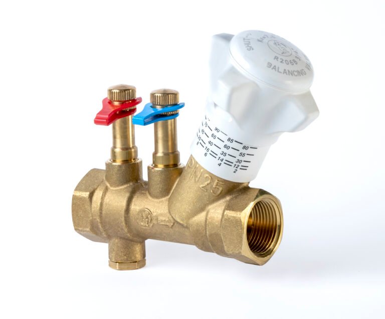
| Manual / Static Balancing Valve | Adjusted to a fixed position during commissioning. The setting is based on design flow and available differential pressure. | Smaller systems with constant-speed pumps, or simple house systems. |
| Automatic / Dynamic Balancing Valve (PICV) | Maintains design flow automatically over a range of pressure conditions. Often combines control and balancing in one body (pressure-independent control valve). | High-rise residential and commercial buildings, variable-flow systems, and projects with variable-speed pumps. |
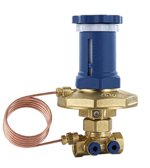
| Differential Pressure Control Valve (DPCV) | Controls the differential pressure across a branch or group of terminals, keeping it within a specified range. | Systems with large pressure fluctuations where stable conditions at the terminal units are critical. |
3. How Do Balancing Valves Work?
Balancing devices work by creating a controlled pressure drop in the hydronic circuit. When the valve is throttled, the resistance increases and the flow is reduced. Engineers size and select the valve based on design flow and the differential pressure available in that branch.
A simplified sizing relation used in hydronic design is:
Q = Kv × √ΔP

Where:
Q  = Flow rate (m³/h)
Kv = Valve flow coefficient
ΔP = Pressure drop across the valve (bar)
Automatic or dynamic valves use internal mechanisms (such as springs and diaphragms) to adjust their opening in response to pressure variations, keeping the flow through the device nearly constant.
4. Static vs. Dynamic Balancing
Choosing between static and dynamic balancing depends on system type and performance requirements:
- Static balancing devices are ideal for simple systems with constant-speed pumps. They are cost-effective but their performance is sensitive to pressure changes elsewhere in the system.
- Dynamic balancing devices maintain stable flow even when pumps ramp up or slow down. They are well suited to larger, energy-efficient buildings using variable-speed pumps and demand-based control strategies.
In many North American cold-climate projects (Ontario, Québec, New York, New England, Chicago, etc.), consultants increasingly prefer dynamic valves combined with variable-speed pumping to meet energy codes and comfort expectations.
5. Key Benefits of Hydronic Balancing
- More uniform temperatures across all zones and apartments
- Fewer hot/cold complaints from occupants
- Lower pump power and reduced electricity use
- Improved delta-T across coils, allowing boilers, chillers, or heat pumps to operate more efficiently
- Less noise in risers, coils, and terminal units due to lower pressure fluctuations
- Supports ASHRAE 90.1 requirements for proportionately balanced hydronic systems
Industry studies and simulations show that optimizing hydronic distribution – including proper balancing and pump control – can reduce heating and cooling energy use by roughly 15–30% in many commercial buildings, especially those with older or poorly tuned systems.
6. Common Problems Without Proper Balancing
- Overheating of units near the mechanical room while remote units remain under-heated
- Unstable control at coils because of excessive pressure variations
- Low delta-T on the chilled or hot-water side, leading to oversized flow rates and poor equipment efficiency
- High pump head and unnecessary electricity consumption
- Short-cycling of boilers, chillers, or heat pumps due to poor distribution
- Long commissioning times and repeated call-backs from building owners
7. Sample Balancing Valve Calculation
The following is a simplified example of how a balancing valve can be sized for a branch in a hydronic heating system.
- Design flow (Q): 0.80 m³/h (≈ 3.5 gpm)
- Available pressure drop across the valve (ΔP): 0.10 bar (≈ 10 kPa)
Re-arranging the sizing formula:
Q = Kv × √ΔP

Kv = Q / √ΔP

Kv = 0.80 / √0.10 ≈ 0.80 / 0.316 ≈ 2.5
In this case, you would select a valve size and setting with a Kv value close to 2.5 at the recommended preset position. At design conditions, the flow will then be approximately 0.80 m³/h. During commissioning, the technician verifies this using pressure ports and a balancing instrument.
8. Cold-Climate Example: Ontario, Québec & U.S. Northeast
In cold-climate cities such as Toronto, Montréal, New York, Boston, and Chicago, hydronic heating is common in both houses and multi-unit buildings. Heating can easily represent 40–60% of total building energy use in these regions, depending on building type and envelope performance.
Several studies and case projects in cold climates have shown that:
- Unbalanced hydronic systems can increase energy use by 20–30% due to over-pumping, low delta-T, and poor coil performance.
- Low delta-T syndrome forces boilers, chillers, or heat pumps to run at lower efficiency and limits available plant capacity.
- Retrofitting hydronic systems with proper balancing and modern controls in existing buildings has delivered measured savings in the range of 15–30% on space heating energy, while improving comfort.
For example, consider a 20-storey condo building in a cold-climate city:
- Unbalanced system: pump is oversized to “force” hot water to remote apartments; delta-T on the heating loop drops to 10°C, and some risers overheat while others are cold.
- After balancing and variable-speed pump control: delta-T improves to 15–18°C, pump head is reduced, and annual pumping energy drops significantly while boilers operate in a more efficient temperature range.
In this type of scenario, it is realistic for a properly balanced system with variable-speed pumping to achieve heating energy savings on the order of 15–25% compared with an unbalanced, constant-speed baseline.
9. Insulation, Heat Pumps & Balancing – How They Work Together
Insulation, efficient equipment, and hydronic balancing are complementary – they do different jobs in the same energy-saving chain:
- Insulation and air sealing reduce heat loss through walls, windows, and roofs.
- Efficient heat sources (condensing boilers, air-to-water or water-to-water heat pumps) reduce the energy needed to produce each unit of heat.
- Hydronic balancing ensures that this heat is delivered evenly and efficiently to every room and apartment without over-pumping or short-cycling.
In houses and small buildings that use hydronic radiators or floor heating with a heat pump, balancing helps keep return-water temperature low and stable. This is critical because heat pumps are more efficient (higher COP) when the required temperature lift is smaller. A well-balanced distribution system can therefore help a heat pump system operate closer to its optimal COP throughout the heating season.
In many cold-climate retrofit projects, combining envelope improvements (insulation and windows) with hydronic optimization and modern controls has resulted in total heating energy reductions in the range of 30–40%, sometimes higher when the original system was in poor condition.
10. Download: Hydronic Balancing Valve Calculators (Excel)
To support engineers, contractors, and designers working in cold-climate hydronic systems, we provide two free Excel tools:
- Basic Hydronic Balancing Valve Flow Calculator – for quick sizing using Q, ΔP, and Kv.
- Advanced Hydronic “Pro” Calculator – includes flow, delta-T, approximate pump power, and a simple before/after comparison of balanced vs. unbalanced scenarios.
Download the calculators:
Download Basic Hydronic Flow Calculator (Excel)
Download Advanced Hydronic Pro Calculator (Excel)
11. References
- ASHRAE Standard 90.1 – “Hydronic systems shall be proportionately balanced in a manner to first minimize throttling losses; then the pump impeller shall be trimmed or pump speed shall be adjusted to meet design flow conditions.”
- Technical papers and case studies on hydronic system optimization and model-based control in cold climates showing heating energy savings up to approximately 30% compared with traditional control or poorly balanced baselines.
- Industry white papers and manufacturer guidance describing how unbalanced water loops and low delta-T lead to over-pumping, reduced plant efficiency, and increased energy use in large hydronic systems.
- Canadian and North American research on hydronic systems in cold climates (Ontario, Québec, U.S. Northeast and Midwest) demonstrating the importance of proper distribution, control, and balancing for both boiler- and heat-pump-based systems.
If you would like project-specific support for a building in Ontario, Québec, or the northern U.S., the ValveAtlas team can help with product selection and hydronic balancing strategies.